Meshedit
July 2020Overview
Give a high-level overview of what you have implemented in this assignment. Think about what you have built as a whole. Share your thoughts on what interesting things you have learned from completing this assignment.
In this assignment, we were given a skeleton of a mesh editor. A mesh is a topological representation of an object in computer graphics pipeline.
The tasks in the assignment (task 3 and onwards) involve manipulating the mesh elements and implement some basic operations like edge flipping, edge splitting, and upsampling of the mesh.
In task 1 and 2 we implement bezier curve, and surface approximation through de Casteljau algorithm.
With the tasks in the assignment completed, we have a working MeshEditor that can render .dae files containing polygon mesh representations and allows a user to visualize the mesh operations that were implemetned as part of the assignment.
Mesh elements are represented in the code as a std::list<types>. Although the assignment attempted, and abstracted away most of the intricacies of the C++, I still got to experience the delicacy of manipulating the elements in the memory. It was fun!
Task 1
Briefly explain de Casteljau’s algorithm and how you implemented it in order to evaluate Bezier curves.
We are given N elements as the initial control points as a parameter for the function BezierCurve::evaluateStep(...) which on each call evalutes each step in the de Casteljau’s algorithm.
The de Casteljau’s algorithm works by obtaining N-1 points from N points in each step of the algorithm, until we reach a single point. N-1 points are obtained by interpolating the adjacent points in the input list.
Interpolation parameter t is evaluated from 0 to 1, and the point calculated from the algorithm is used to draw the final curve
We implement the above said function BezierCurve::evaluateStep(...) in the assignment.
Take a look at the provided .bzc files and create your own Bezier curve with 6 control points of your choosing. Use this Bezier curve for your screenshots below.
Show screenshots of each step / level of the evaluation from the original control points down to the final evaluated point. Press E to step through. Toggle C to show the completed Bezier curve as well.
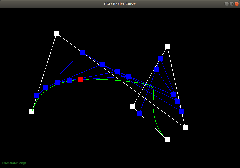
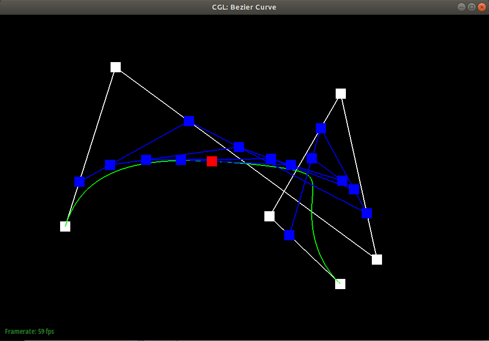
I’ve created another .bzc file that has 6 control points, and took screenshots of how the Bezier curve turned out.
Show a screenshot of a slightly different Bezier curve by moving the original control points around and modifying the parameter via mouse scrolling.
Also please see the above gif! The control points are moved in the below images from the gif version.
Task 2
Briefly explain how de Casteljau algorithm extends to Bezier surfaces and how you implemented it in order to evaluate Bezier surfaces.
Intuitively, we evaluate Bezier curves along one “grain”. N x 1 control points are evaluated in the method BezierPatch::evaluate1D(...) which repeated calls BezierPatch::evaluateStep(...). Then the N points along the other “grain” of the patch are evaluated as the control points. The resulting evaluated curve is a slice of the final Bezier surface, and we continue the same until we have a whole surface which is implemented in BezierPatch::evaluate(...).
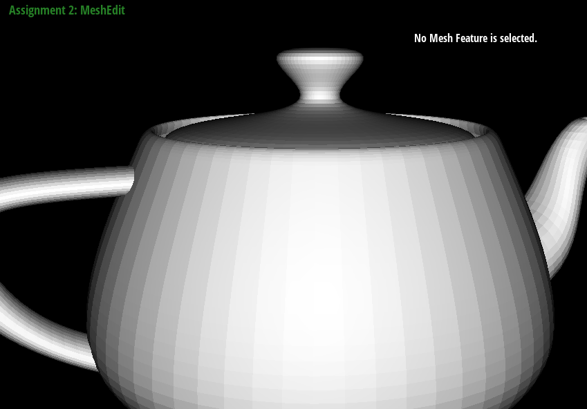
Show a screenshot of bez/teapot.bez (not .dae) evaluated by your implementation.
Task 3
Briefly explain how you implemented the area-weighted vertex normals.
The area-weighted vertex normal is obtained by traversing the triangles around a vertex and as the name suggests, by calculating the area-weighted normals.
Each face class of a triangle contains a unit face normal, computed via the area vector as the comment mentions in the code.
To get to the normal of the face, we have to traverse the triangles with halfedge elements. From the vertex parameter input to the class method Vertex::normal(...), we take one of the halfedge that originates from the vertex. Using twin() and next() of the halfedge, we can move to the next triangle until we reach back the original triangle–this is a nice property of 2D manifold that we utilize. Using face() we can access the face element of that halfedge.
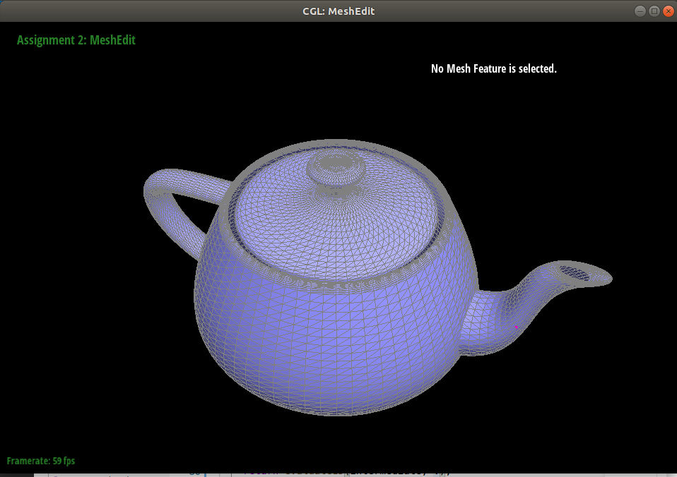
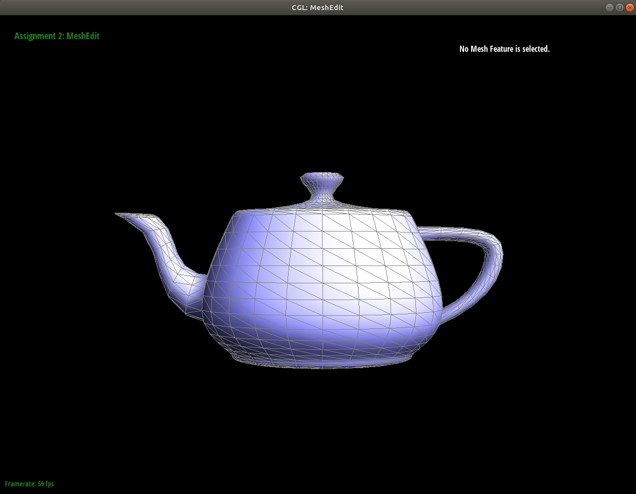
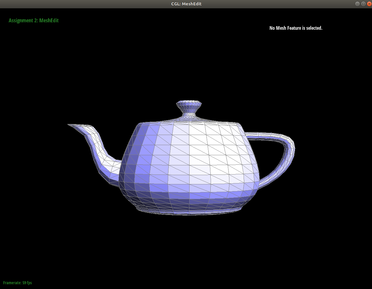
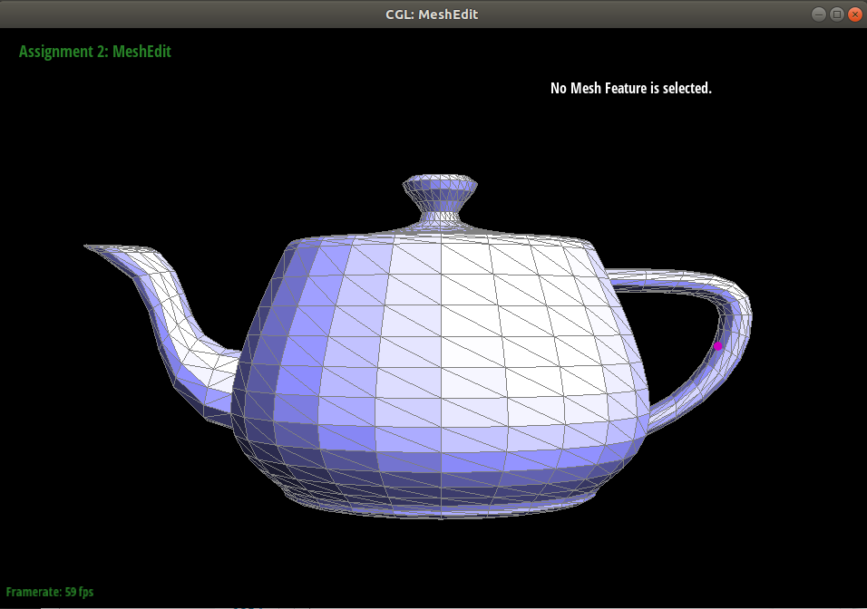
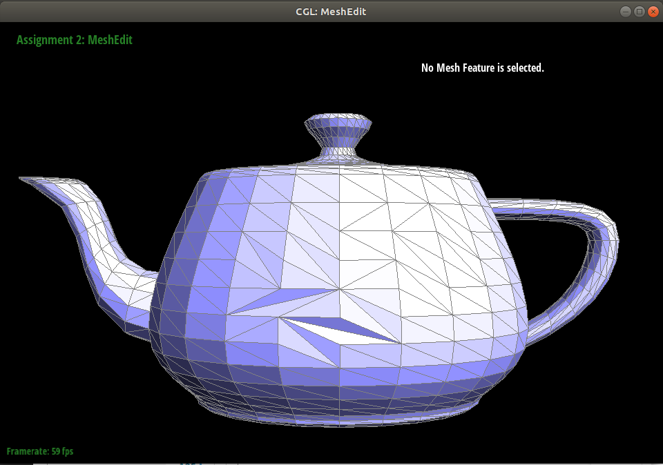
Show screenshots of dae/teapot.dae (not .bez) comparing teapot shading with and without vertex normals. Use Q to toggle default flat shading and Phong shading.
Task 4
Briefly explain how you implemented the edge flip operation and describe any interesting implementation / debugging tricks you have used.
Conceptually, the edge flip is quite intuitive and simple. To implement it in the mesh data structure, is another story.
This task is the first task in the assignment that has involved pointer access operation. To translate that abstract concept into the code, it was helpful to one-by-one, link the concept to element in the mesh data structure.
The implementation is quite simple, after checking whether the edge is a boundary edge, reassign all the necessary components correctly and the meshEdit visualizer will correctly draw the result.
Show screenshots of a mesh before and after some edge flips.
Write about your eventful debugging journey, if you have experienced one.
The journey was a bit straightfoward, thankfully. The biggest thing that helped, as recommended by the project specification, was to draw out the elements that need to be updated when the edge is flipped.
Task 5
Briefly explain how you implemented the edge split operation and describe any interesting implementation / debugging tricks you have used.
The implementation of the edge split operation is similar in nature to the Task 4, however, this operation involves introduction of some new elements into the mesh data structure representation.
I’ve used the following diagram using asciiflow.com to guide whether a correct set of the new elements were introduced, and whether the re-assignments were done correctly. Having a visual representation to go with the code was helpful.
  //
  //                           +
  //                         X | X
  //                           |
  //                    X    ^ | +    X
  //                         | | |
  //               X         | | |          X
  //                      h2 | | | h1
  //         X               | | |                X
  //              newh3      + | v     newh5
  //  X     +----------->      |      +--------->       X
  // +-------------------------X-------------------------+
  //  X          newh4     e2  |newV <----------+ e3   X
  //        <-----------+    ^ |  +     newh6
  //       X                 | |  |              X
  //             newf1  newh2| |  |newh1  newf2
  //              X          | |  |         X
  //                         | |e1|
  //                    X    + |  v   X
  //                           |
  //                         X | X
  //                           +
Show screenshots of a mesh before and after some edge splits.
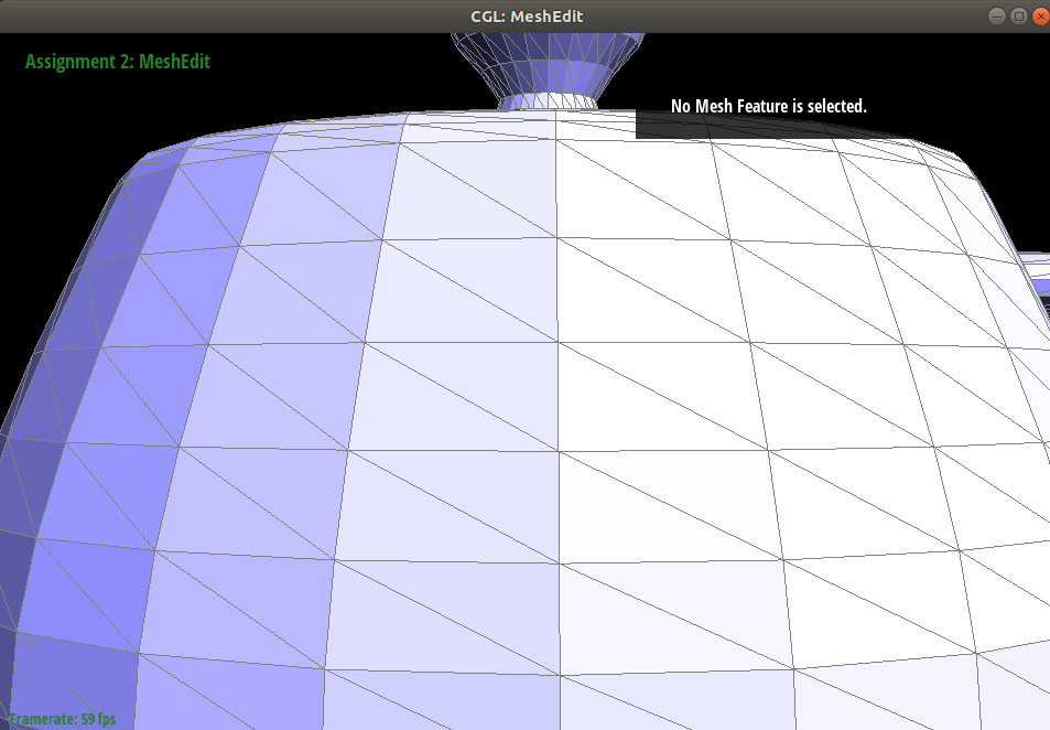
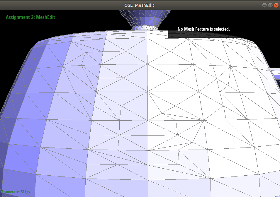
Show screenshots of a mesh before and after a combination of both edge splits and edge flips.
Write about your eventful debugging journey, if you have experienced one.
This task was a bit more involved, but the Halfedge class method setNeighbors(...) helped a lot in saving lines of pointer traversal. The initial implementation seemed to work, but after splitting multiple edges, some of the previously splitted adjacent triangles suddenly lost faces.
I tracked down the issue to not setting the existing halfedges’ face address to the new faces that were introduced while splitting an edge.